

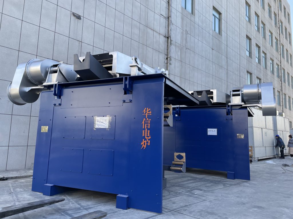
Intermediate frequency electric furnace widely used in steel casting
Intermediate frequency electric furnaces are widely used in steel, casting, special steel and other related fields. Different application fields have different requirements for intermediate frequency power supplies. Only on the basis of mastering the basic working principles of these circuits and the basic characteristics of power devices can they be rapid and accurate Analyze and judge the cause of the failure, and take effective measures to eliminate the failure.
Water-cooled cable: The function of the water-cooled cable is to connect the intermediate frequency power supply and the induction coil. It is formed by twisting each diameter Φ0.6-Φ0.8 copper wire. For a 500 kg electric furnace, the cable cross-sectional area is 480 square millimeters, and for a 250 kg electric furnace, the cable cross-sectional area is 300 to 400 square millimeters. The outer hose of the water-cooled cable adopts a pressure rubber hose with a pressure resistance of 5 kg, which is filled with cooling water. It is a part of the load circuit. It is subjected to tension and torsion during work. The connection is broken. The breaking process of the water-cooled cable generally involves cutting off most of the parts first, and then quickly breaking the unbroken part during high-power operation. At this time, the intermediate frequency power supply will generate a high overvoltage. If the overvoltage protection is unreliable, Will burn out the thyristor. After the water-cooled cable is disconnected, the intermediate frequency power supply cannot start to work. If you restart repeatedly without finding out the cause, the intermediate frequency voltage transformer is likely to be burned out. When checking the fault, use an oscilloscope to clamp the oscilloscope probe at both ends of the load, and observe whether there is an attenuation waveform when the start button is pressed. When confirming that the cable is broken, first disconnect the water-cooled cable from the capacitor output copper bar, and measure the resistance value of the cable with a multimeter (200Ω block). The resistance value is zero when it is normal, and it is infinite when it is disconnected. When measuring with a multimeter, the furnace body should be turned to the dumping position to make the water-cooled cable fall off, so that the broken part can be completely separated, so that it can be correctly judged whether the core is broken.
Through the above inspections, most of the causes of failures can generally be found, and then the control power supply can be turned on for further inspections.
The main circuit of the power supply of the intermediate frequency electric furnace has two kinds of manual and automatic closing. For automatic closing systems, the power cord should be temporarily disconnected to ensure that the main circuit will not be closed. After turning on the control power, you can check the following aspects.
1. Connect the oscilloscope probe to the gate and cathode of the rectifier thyristor, set the oscilloscope to power synchronization, press the start button to see the trigger pulse waveform, it should be a double pulse, and the amplitude should be greater than 2V. Press the stop button once and the pulse will disappear immediately. Repeat six times and look at each thyristor. If there is no pulse at the gate, you can move the probe of the oscilloscope to the primary side of the pulse transformer to take a look. If there is a pulse on the primary side but not on the secondary side, the pulse transformer is damaged, otherwise there is a problem It may be in the transmission line or the main control board.
2. Connect the oscilloscope probe to the gate and cathode of the inverter thyristor. The oscilloscope is set to internal synchronization. After turning on the control power supply, you can see the inverter trigger pulse. It is a series of sharp pulses whose amplitude should be greater than 2V. Read the pulse period on the time scale of, and calculate the trigger pulse frequency. Normally, it should be about 20% higher than the nominal frequency of the power cabinet. This frequency is called the starting frequency. After pressing the start button, the pulse interval increases and the frequency becomes lower. Normally, it should be about 40% lower than the nominal frequency of the power cabinet. Press the stop button once, and the pulse frequency immediately jumps back to the start frequency. Through the above inspections, it is basically possible to eliminate the failure to start at all. It does not work normally after startup, which is generally manifested in the following aspects:
1. Phase loss of the rectifier: the fault is manifested as abnormal sound during operation, the *** output voltage rises below the rated value, and the strange noise of the power cabinet becomes louder. At this time, the output voltage can be lowered to about 200V, and the rectifier can be observed with an oscilloscope The output voltage waveform of the oscilloscope (the oscilloscope should be placed in synchronization with the power supply). Normally, the input voltage waveform has six waveforms per cycle, and two are missing when the phase is missing, as shown in Figure 2. This fault is generally caused by a rectifier thyristor without trigger pulse or triggering non-conduction. At this time, you should use an oscilloscope to look at the gate pulses of the six rectifier thyristors. Click each gate resistance and replace the thyristor that is blocked or the gate resistance is particularly large.
2. Inverter three bridge arms work: the fault is manifested as the output current is particularly large, the same when the furnace is empty, and the sound of the power cabinet is heavy when the power cabinet is working, after starting, turn the power knob to the minimum position, and you will find the intermediate frequency output The voltage is higher than normal. Use an oscilloscope to observe the voltage waveforms between the anode and the cathode of the four inverter thyristors. Normally, the waveform of each one is shown in Figure 3. If the three bridge arms work, you can see that the waveforms of the two adjacent thyristors in the inverter are normal, and only one of the adjacent two has no waveform, and the other is a sine wave. As shown in Figure 4, KK2 triggers If it is not connected, the waveform between the anode and the cathode is a sine wave; at the same time, the non-conduction of KK2 will cause the KK1 to be unable to turn off, so there is no waveform at the two ends of KK1.
3. Induction coil failure: The induction coil is the load of the intermediate frequency power supply. It is made of a square copper tube with a wall thickness of 3 to 5 mm. Its common faults are as follows:
Water leakage in the induction coil, which may cause ignition between the coil turns, must be repaired in time to operate;
The molten steel sticks to the induction coil, and the steel slag heats up and becomes red, which will cause the copper pipe to burn through. It must be cleaned up in time;
Induction coil turn-to-turn short circuit. This type of fault is particularly prone to occur on small medium-frequency induction furnaces. Because the furnace is small, it is deformed by thermal stress during operation, resulting in a short circuit between turns. The fault is manifested as a large current and a higher operating frequency than usual. .
In summary, in order to use the correct method to repair the intermediate frequency power supply, it is necessary to be familiar with the characteristics and causes of the common failures of the intermediate frequency power supply, so as to avoid detours, save time, remove the fault as soon as possible, and restore the normal operation of the intermediate frequency power supply. , So as to ensure the smooth progress of production.
